text of this document
Page 1
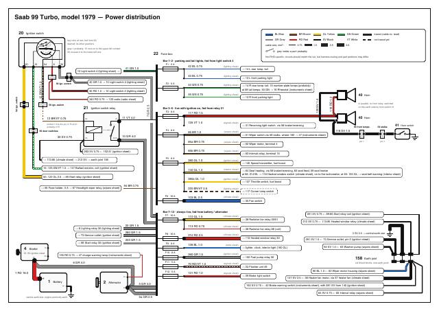
Saab 99 Turbo, model 1979 — Power distribution
20 Ignition switch
key rotor at rest, fed from 30;
dashed: its other positions
BL Blue
BR Brown
GL Yellow
GN Green
traced (cable no. read)
GR Grey
RD Red
SV Black
VT White
not traced yet
cable size, mm²:
0.75
1.5
2.5
4.0
grey = probably: 15 runs on to the upper-left contact,
50 crosses it to the lower-left one
grey inside a part: probably
22 Fuse box
Not RHD-specific: circuits should match the car, but harness routing and part positions may differ.
Bar 1–2 · parking and tail lights, fed from light switch 4
54
X
30
F1 · 5 A
58 ign. switch
12 BR/VT 1.0
10 Light switch 4 (lighting sheet) →
41 GN 1.0
40 GR 1.0 → 10 Light switch 3 (lighting sheet)
58 ign. switch
F2 · 5 A
42 BL 0.75
(lighting sheet)
43 BL 0.75
(lighting sheet)
44 GN 0.75
(lighting sheet)
45 GN 0.75
(lighting sheet)
30 RD 1.0 → 10 Light switch 2 (lighting sheet)
340 RD 0.75 → 122 radio (radio sheet)
7 GR 2.5
58 ign. switch
21 Ignition switch relay
12 BR/VT 0.75
86
87
11 VT 4.0
F3 · 8 A
F4 · 8 A
85
30/51
263 SV 0.75 ← 102:31 (ignition sheet)
F5 · 8 A
15: 123 GN/VT 1.5 → 147 Ballast resistor, coil (ignition sheet)
50: 122 GL 2.5 → 89 Start relay (ignition sheet)
→ 65 Fuse holder, 3 A → 67 Headlight wiper relay (wipers sheet)
40 Horn
→ 13 R front parking light
117 RD 1.5
(signals sheet)
85 BR 1.0
(wipers sheet)
85a BR 0.75
(wipers sheet)
85b BR 0.75
(wipers sheet)
380 GL 1.0
(ignition sheet)
140 GL 1.0
(interior sheet)
380a GL 1.0
(ignition sheet)
220 BR/VT 0.5
(lighting sheet)
103 BL 2.5
(climate sheet)
10 GR 4.0
→ 113:85 (climate sheet) → 212 SV → earth joint 158
→ 14 R rear lamp: tail; 15 number-plate lamps (probably)
at 58 tail lamps: 50 GN → 16 Rheostat (instruments sheet)
in parallel, no horn relay: switched
on the earth side by horn switch 41
40 Horn
printed 1.0 by the pin, 0.75 at 21:
probably 0.75
33 SV 0.75
→ 13 L front parking light
Bar 3–6 · live with ignition on, fed from relay 21
135 VT 1.0
58 door switches
→ 14 L rear lamp: tail
119 RD 1.0
15
120 SV 1.0
50
→ 31 Reversing light switch, via 58 brake/reversing
58 front lamps
58 stalks
pin 1
pin 1
118 SV 1.5
→ 61 Wiper switch via 58 stalks, where 182 → 47 (instruments sheet)
→ 62 Wiper motor, terminal 4
→ 83 Interval relay, terminal 15
→ 140 Speed transmitter, fuel boost
→ 64 Seat heating, via 58 brake/reversing, 60 seat feed, 59 seat heater
at 58: 214 BL → 116 Heated window switch (climate sheet), on to the tachometer; at 60: 150 GL → seat belt warning (interior sheet)
→ 137 Throttle switch, fuel boost
94 BR 0.75
F6 · 16 A
→ 117 Corner lamp switch
→ 35 Fan switch
Bar 7–12 · always live, fed from battery / alternator
F7 · 16 A
→ 8 Lighting relay 30 (lighting sheet)
→ 73 Service outlet (ignition sheet)
→ 89 Start relay 30 (ignition sheet)
4 Starter
20 GR 1.5
280 GR 1.5
F8 · 16 A
110 GL 1.5
→ 38 Radiator fan relay 30/51
(climate sheet)
210 RD 2.5
(climate sheet)
50
30
F9 · 8 A
F10 · 8 A
195 RD 0.75 → 47 charge warning lamp (instruments sheet)
F11 · 5 A
6 GR 4.0
F12 · 5 A
1 RD 16.0
+
D+
1 Battery
−
2 Alternator
5 GR 4.0
B+
212 SV 0.75 ← 113:85 Heated window relay (climate sheet)
→ 38 Radiator fan relay 86 (coil)
3 SV 2.5 → central earth star
→ 113 Heated window relay 30
202 GR 1.5
126 BL 1.0
(radio sheet)
260 GR 1.5
(ignition sheet)
16
16, 50: ignition sheet
201 SV 0.75 ← 89:85 Start relay coil (ignition sheet)
(climate sheet)
113 RD 0.75
(signals sheet)
131 RD 1.0
(signals sheet)
281 SV 1.5 ← 73 Service outlet, pin 2 (ignition sheet)
→ lighter, clock, interior light (160 GL)
→ 102 Fuel pump relay 30
70 RD/VT 1.0
92 SV 1.0 ← 63 Washer pump (wipers sheet)
158 Earth joint
six linked blocks: one earth point
→ 23 Flasher unit 49
90 BL 1.0 ← 62 Wiper motor housing (wipers sheet)
→ 29 Brake light switch
107 SV 2.5 ← 36 Heater fan motor, via 57 heater fan (climate sheet)
192 SV 0.75 ← 42 Brake warning switch (instruments sheet), with 381 SV from 140 (ignition sheet)
83 SV 0.75 ← 83 Interval relay (wipers sheet)
central earth star: engine and body earth
5a GR 2.5
41 Horn switch
Page 2
Saab 99 Turbo, model 1979 — Lighting circuit
ignition switch connector, 12-pole
58
30 RD 1.0
20 Ignition switch
X
FRONT
40 GR 1.0
6-5: top position, town light
(S/N/DK only). This car has
no town light (check E21b);
wires on 6-5: check D11
car’s right side at top
X: live with key on (red)
30
6
11/12 Headlamp R
2
3
10 Light switch
5
top: off (town light S/N/DK) /
parking / headlamps
1
117 Corner lamp switch
dash switch with pilot lamp; probably wired as drawn
24 GL 1.0
58
118 SV: horns
4
222a BR/VT 0.5
REAR
Combi Coupé (this car)
221 BR/VT 0.5
220 may be GL (check E19b)
2
3
41 GN 1.0
223 SV 0.75 → clock 49
earth, with 128 SV,
then via 48 and 129
to earth (radio sheet)
front lamp connector
1
4
7 GR 2.5
26 VT 1.0
29 SV 1.0
30: battery in (grey)
77 BL/VT: indicator 27
220 BR/VT 0.5 ← fuse 5
(power sheet)
138 BL ← reversing 31
Rear lamp cluster R
Supply bar, fuses 7–12: always live
fed from battery via 5 GR 4.0 + 5a GR 2.5
28 indicator
79 RD/VT: signals sheet
58 tail lamps
44 GN 0.75
221a BR/VT 0.5
14 tail
1
59 number plate
(probably at the tailgate)
Fuse 2 · 5 A
45 GN 0.75
50 GN 0.75 →
rheostat 16,
panel lighting
(instruments sheet)
13 Parking R
twin bulb 21/5 W: 5 W parking 13,
21 W corner lamp 118
28 indicator: signals sheet
lower bulb: side back-up light
133 RD: signals sheet
30 brake
137 VT: signals sheet
32 reversing
earth: check R3
47 Instrument
main-beam
warning lamp
149 SV 0.75
139a VT 0.75
47 GN 0.75
47a GN 0.75
361 SV 1.0 → washer pump 63 earth (wipers sheet)
221 BR/VT 0.5
8 Lighting relay
13 Parking L
360 SV 0.75
15 Number-plate lamps
Fuse 1 · 5 A
43 BL 0.75
twin bulb 21/5 W: 5 W parking 13,
21 W corner lamp 118
27 indicator: signals sheet
lower bulb: side back-up light
Rear lamp cluster L
drawn at rest: lights off, stalk released
22 Fuse box
E
(fuses 1–2 and bar 7–12 shown)
D
F
27 BL/VT 0.75
A
148 SV 0.75
139 VT 0.75
K1
B
136 VT: signals sheet
32 reversing
132 RD: signals sheet
30 brake
C
K2
58 tail lamps
G
42 BL 0.75
H
14 tail
2
27 indicator
76 BL/VT: signals sheet
56a
56b
S
31
86
30
11/12 Headlamp L
25 BL 1.0
28 SV 1.0
58 stalks
9
13 SV 0.75
earth: check R3
Cable key: number · colour · mm²
31 GL 0.75
23 GR 1.0
→ 113:85 (climate sheet), earth via 212 SV and joint 158
20 GR 1.5
32 VT 0.75
115 SV 0.75 ← 39 Thermostat switch (climate sheet)
8 Lighting relay states
state
latching dip/main + flash; each path starts at terminal 30
coils pulled
path (letters in 8)
lights
1 lights off
none
30 → C → B → A
nothing: flash blade A–D open
2 headlamps on
K2
30 → C → E → F → H → 56b
dipped
3 main, latched
K2, K1 pulse
30 → C → E → F → G → 56a
main + dash lamp 47; next pulse: dipped (check D13)
4 flash, lights off
K1, stalk held
30 → C → B → A → D
main on the car (check D9); D drawn on 56b: check D12
9 Dip/flash stalk
pulse on S toggles dip/main;
flash works with ignition off
32 VT 0.75
cable size, mm²:
0.75
1.5
BL Blue
BR Brown
GL Yellow
GN Green
traced (cable no. read)
GR Grey
RD Red
SV Black
VT White
not traced yet
grey inside a part: probably
2.5
faded blade: position when pulled
Headlamps need the ignition on (except the flash, stalk 9); parking/tail lights do not: light switch 2 is fed from ignition
switch X, light switch 3 from the always-live bar. Headlamps are unfused: relay 30 is fed straight from the supply bar (20 GR 1.5).
Not RHD-specific: circuits should match the car, but harness routing and part positions may differ.
All bulbs in a lamp housing share its one earth (rear lights: check R3). The rear is drawn for the Combi Coupé (this car): fuse 2 probably also
feeds the number-plate lamps through 44 and connector 59. These lamps, 59 and 47/47a (dashed): not yet checked on the car (checks R1, R4, R5).
Corner lamps (dashed): dash switch 117 with pilot lamp, fed from fuse 5 (checks E19, F4); wiring probably as drawn,
colours: check E19b. 221 reaches the left housing through pin 2 of front lamp connector 58; 222a branches off for the right.
One bulb, two filaments: 5 W parking 13 from light switch 10, no ignition; 21 W corner lamp 118 from 117, ignition on (check E21).
Not drawn: a rear fog lamp (check E23) or a relay that cuts the corner lamps on dipped beam (check E22); probably neither is fitted.
Relay 8: the car flashes the main beams (check D9), but flash contact D is drawn on 56b (dipped); which pin carries main: check D12.
4.0
Page 3
Saab 99 Turbo, model 1979 — Ignition, starting and fuel injection
393 SV 1.5
7 GR 2.5 ← bar 7–12
(power sheet)
30
58 door switches
5 Coil
147 Ballast resistor
58 engine
6 Distributor
123 GN/VT 1.5
0.4 Ω
0.6 Ω
31
screened
390
123b GL 1.5
15
15
391
122 GL 2.5
row 6
50
31d
146
7
Ignition control unit
pin 4
392 SV 0.75
15
1
58 ign. switch
row 1
202 GR 1.5 ← bar 7–12 (always live)
(power sheet)
89
Start relay
201 SV 0.75 → earth joint 158 (power sheet)
85
87
1
2
3
4
157 Spark plugs
123d GN/VT 1.0
124 BL 1.5
87a
1 RD 16.0 ← battery +
(power sheet)
261a GR 0.75
190 SV 0.75 ← fuel level transmitter 46 (instruments sheet)
378 GN/VT 0.75
30
16
30
394 GN/VT 1.0
86
16
103 Fuel pump
122a GL 2.5
50
15
87
261 GR 2.5
58 door switches
row 4
262 SV 2.5
M
31
4 Starter
57 fuel pump
electronics
377 GN/VT 0.75 ← 58 engine pin 4,
switch side (top of sheet)
16
102
60 tank earth
265 GR 0.75
Fuel pump relay
95 Aux. air regulator
144 Pressure switch (overboost)
281 SV 1.5 → earth joint 158
(power sheet)
31
58 engine
pin 2
30
263 SV 0.75 → relay 21:85 (power sheet)
3 4 5
High-speed fuel boost
2 1 6
Richens the mixture above about 130 km/h (140) or at 62° throttle (137).
W
280 GR 1.5 ← bar 7–12
(power sheet)
266 SV 0.75
284 BL 0.75
284a BL 0.75
380 GL 1.0 ← fuse 5
(power sheet)
191 SV 2.5
heated; on with the pump
100 SV 0.75 ← relay 67:87 (wipers sheet)
15
142 Solenoid valve
260 GR 1.5 ← fuse 10
(power sheet)
382 BL 0.75
140
Speed transmitter
267 GR 0.75
282 GL 1.0
283 GN/VT 0.75 ← 58 engine pin 4,
switch side (top of sheet)
58 engine, pin 1
relay side probably
GN 1.0 (check E1)
96 Warm-up regulator
on the car: speedometer cable, engine bay (check E7)
heated
-31
204 GL 0.75 → tachometer
110 (instruments sheet)
Pins in their order round the socket (check E11):
1 battery +, 2 earth, 3 start, 4 ignition +15,
5 engine speed (284a from 102, 204 to the tachometer),
6 empty.
268 SV 0.75
92 Thermo-time switch
383 GR 0.75
380a GL 1.0 ← fuse 5
(power sheet)
73 Service outlet (TSI)
on the car: front of the engine, on the control
pressure line (check E7); 382 and 383 on one contact,
earth on the other (check E12)
381 SV 0.75 → brake warning switch 42 (instruments sheet)
→ 192 SV → earth joint 158 (power sheet)
271 RD 1.0
20 Ignition switch
94 Cold-start valve
137 Throttle switch, 62°
58 engine, pin 3
273 GR 0.75
272 BR 0.75
fed while cranking
earths the valve when cold
BL Blue
GR Grey
cable size, mm²:
BR Brown
GL Yellow
RD Red
0.75
traced (cable no. read)
grey inside a part: probably
SV Black
1.5
2.5
GN Green
VT White
4.0
HT lead
checked on the car
Overboost cut: pressure switch 144 (closed at rest) is in the fuel pump relay’s feed (15). If it opens, the relay drops out and the pump stops.
263 SV (pump relay 31) goes to relay 21, probably its 85, and on to earth joint 158.
The pump relay also takes an engine-speed signal from 146 (284 BL), which normally stops the pump when the engine isn’t turning.
100 SV, headlight wiper relay 67’s earth, also lands on 102:31. 201 SV goes to 158 directly.
Start relay 89: its coil is earthed directly (201 SV), so it pulls in whenever the key is at start. It feeds starter terminal 50 (the solenoid)
123d (+15 for 146) leaves engine connector 58 pin 4 on the 147 side, before the ballast
from the always-live bar, and 87a feeds 394 to the joint of 147’s two resistors, bypassing the 0.4 Ω one while cranking (the 0.6 Ω stays in).
resistor. 377 and 283 leave the pin on the switch side, each its own lead beside 123.
92 may also have a second element between its two terminals (perhaps a second heater); it is not drawn, as what it is is not known.
102’s joined bottom pair (marked 31) takes the speed signal (284, 284a): probably terminal 1.
Sender cable 390/391 is screened; 392 SV earths the screen. Pin and row numbers of the 58 connectors are our own count, top to bottom (engine: check E1).
381 SV (140’s earth) lands on 42’s earth side, probably spliced into 192 SV there.
Not RHD-specific: circuits should match the car, but harness routing and part positions may differ.
266, 268, 392 and 393 SV go to the central earth star. Relay 21, joint 158: power sheet.
Page 4
Saab 99 Turbo, model 1979 — Instruments and warning lamps
44 Oil warning switch
engine connector 58, pin 5
184 BL 1.0
tail lamp connector 58, rows 4 and 5
186 BR 0.75
185 GR 0.75
47 Combination instrument
45 Temperature transmitter
11
12
3
engine connector 58, pin 6
183 GL 1.0
9
C°
oil
46 Fuel level
B
low fuel
transmitter
fuel sender connector 57
temperature
fuel gauge
190 SV 0.75 → tank earth connector 60 → 191 SV 2.5
→ earth, with pump earth 262 (ignition sheet)
tachometer connector 60
204 GL 0.75 ← service outlet 73, pin 5, beside 284a (ignition sheet)
charge
195 RD 0.75
brake
1
D+
203 BR 0.75 ← heated window switch 116 (climate sheet)
r/min
2 Alternator
50 GN 0.75 ← fuse 2 (right park, tail, plate), off 44 GN
at tail lamp connector 58 (lighting sheet)
main beam
indicator
110 Tachometer
16 Rheostat (dimmer)
179 SV 0.75 ← 47 terminal 4 (above)
7
51 GN 0.75
53 GN 0.75
55 GN 0.75
54 SV 0.75
19 Glove compartment and heater control lights
(drawn as one lamp; one bulb or two: check D18)
6
2
4
59 panel light connector
52 SV 0.75 → hazard switch 25’s lamp terminal
→ 69 SV 0.75 → earth (signals sheet)
Panel lighting (sidelights on; dimmed by 16)
17 Switch lights (two; which switches: check D18)
18 Instrument panel light (two)
5
179 SV 0.75 → panel light connector 59 (lower left), then 52 → 69 → earth
18
56 SV 0.75
58 SV 0.75
57 GN 0.75
62 SV 0.75
18
182 BR/VT 0.75 ← fuse 4, off 85 BR at stalk switch connector 58, pin 5 (wipers sheet)
71 GN/VT 0.75 ← 23 flasher unit C (signals sheet)
ignition switch connector 58, row 7
187 VT 0.75
188 VT 0.75
188 VT 0.75
61 GN 0.75
17
60 SV 0.75
27 BL/VT 0.75 ← 8 lighting relay 56a (lighting sheet)
59 GN 0.75
19
BL Blue
BR Brown
GL Yellow
GN Green
GR Grey
RD Red
SV Black
VT White
43 Handbrake switch
42 Brake warning switch
381 SV 0.75 ← speed transmitter 140, -31 (ignition sheet)
192 SV 0.75 → earth joint 158 (power sheet)
Inside 47 (its own terminal numbers): a + rail from 2 (182) feeds both gauges and the oil (11), low-fuel (12), brake (5) and charge (1) lamps; an earth rail to 4 (179) takes the gauges’ third leads and the main-beam (7) and indicator (6) lamps.
Oil and temperature wires pass engine connector 58, pins 5 and 6 (our own count, top to bottom; check E1); the fuel sender wires pass tail lamp connector 58 (rows 4 and 5) and fuel sender connector 57 (3-pole).
Charge lamp: 195 RD 0.75 from alternator D+. Main beam: 27 BL/VT from lighting relay 8. Indicator: 71 GN/VT from flasher 23. Brake: 187 VT, then 188 VT to handbrake switch 43 and brake warning switch 42; either earths it.
cable size, mm²:
0.75
traced (cable no. read)
grey inside a part: probably
1.5
2.5
4.0
Supply: 182 BR/VT from fuse 4, branching off the wiper feed 85 BR at stalk switch connector 58. Tachometer: signal 204 GL from service outlet 73 pin 5 (beside 284a), through tachometer connector 60; supply probably 203 from heated window switch 116.
Earth: 47’s 4 (179 SV) goes through panel light connector 59 and 52 SV to hazard switch 25’s lamp terminal, which 69 SV earths (signals sheet); the panel lamps (lower left) earth the same way.
Fuel level transmitter 46: its third lead, 190 SV (no terminal name printed), is its earth. It meets the pump’s earth 262 at tank earth connector 60 and goes on as 191 SV 2.5 to earth, probably near the tank.
44 and 45 are drawn with the sender symbol (heavy square with a diagonal, not a winding), each with its own earth lead (no cable number). 44 probably earths the oil lamp at low oil pressure; 45 is probably a resistance that falls as the coolant warms.
Not RHD-specific: circuits should match the car, but harness routing and part positions may differ.
Page 5
Saab 99 Turbo, model 1979 — Indicators, hazards, brake and reversing lights
74 GN 1.0
Indicators and hazards
73 GN 1.0
71 GN/VT 0.75 → 47 dash indicator
lamp (instruments sheet)
Fuse 11 · 5 A
11
52 SV 0.75 ← panel light
connector 59: instrument
earth 179 and the panel
lamps (instruments sheet)
+
54
70 RD/VT 1.0
always-live bar
49
C
49a
24 Indicator switch
69 SV 0.75
31
earth point shared
with 129, 157, 341 SV
25 Hazard switch
23 Flasher unit
R
L
L
R
REAR
68 RD/VT 1.0
Combi Coupé (this car)
75 BL/VT 1.0
67 BL/VT 1.0
Rear lamp cluster, right
FRONT
78 RD/VT 1.0
79 RD/VT 1.0
28 Rear indicator, right
car’s right side at top
stalk switch
connector 58
28 Front indicator, right
in the front lamp housing with parking light 13
80 RD/VT 1.0
ignition switch
connector 58
14 Tail light, right
44 GN from fuse 2 (lighting sheet)
361 SV 1.0 → washer pump 63 (wipers sheet)
133 RD 0.75
30 Brake light, right
137 VT 0.75
32 Reversing light, right
27 Front indicator, left
in the front lamp housing with parking light 13
77 BL/VT 1.0
360 SV 0.75
front lamp
connector 58, pin 3
Brake and reversing lights
Rear lamp cluster, left
29 Brake light switch
Fuse 12 · 5 A
12
131 RD 1.0
brake and reversing
light connector 58
132 RD 1.0
32 Reversing light, left
132 RD 1.0
30 Brake light, left
always-live bar
14 Tail light, left
42 BL from fuse 1 (lighting sheet)
76 BL/VT 1.0
Fuse 3 · 8 A
3
135 VT 1.0
27 Rear indicator, left
ignition-on bar
31 Reversing light switch
→ via front lamp connector 58 to the side back-up lights (lighting sheet)
138 BL 1.0
136 VT 1.0
BL Blue
BR Brown
GL Yellow
GN Green
GR Grey
RD Red
SV Black
VT White
cable size, mm²:
0.75
traced (cable no. read)
1.5
2.5
4.0
Flasher 23 is fed on 49 from fuse 11 (always-live bar). 49a (73 GN) feeds the hazard switch’s +, which feeds the indicator switch’s 54; C (71 GN/VT) works the dash indicator lamp. Its 31 is probably earthed through the mounting (grey).
Switches are drawn at rest. Pressed, hazard switch 25 closes its lamp, R and L contacts together, so + feeds both sides (68 RD/VT, 67 BL/VT).
Terminals: hazard switch 25 has +, R, L and one for its lamp (markings: check D4); indicator switch 24 has 54, R and L. 73 GN and 74 GN both land on +.
25’s lamp contact is open at rest: the lamp stays dark with the indicators and blinks with the hazards (check D7). Grey: the end of 29’s blade and its right contact; probably open at rest.
25’s lamp terminal: 69 SV goes to earth and 52 SV to panel light connector 59, where the instrument earth (179 from 47) and the panel lamps join it, so 69 earths them too.
24’s own outputs are 75 BL/VT and 78 RD/VT, through stalk switch connector 58 to ignition switch connector 58. 76/79 (rear) pass ignition switch connector 58
and run to the rear clusters with no other connector; 77/80 (front) leave 75/78 just before ignition switch connector 58, and 77 then passes front lamp connector 58 (pin 3).
grey inside a part: probably
Front lamps on the left, rear lights on the right, the car’s right side at the top, as on the lighting sheet. Each lamp housing has one earth for all its bulbs; the parking lights and the tail-light feeds are on the lighting sheet.
Rear lamp clusters (3-door Combi Coupé): four bulbs each, probably in the order drawn. No earth lead is printed for them (check R3): each bar goes to earth in grey.
132 and 136 run to the left cluster; 133 and 137 leave its brake and reversing feeds for the right one (at the cluster, probably; the dots are drawn short of it, for room).
138 BL, from 31’s switched side, feeds the front housings’ side back-up lights (check E16). Brake and reversing light connector 58: 132, 135 and 138 pass on its pins 2, 3 and 4 (counted top to bottom); pin 1 is 140 GL (interior sheet).
Not RHD-specific: circuits should match the car, but harness routing and part positions may differ.
Page 6
Saab 99 Turbo, model 1979 — Radio, speakers and accessory feeds
122 Radio junction box, 8-pole
1
5
2
6
3
7
4
8
4, 8 unused
341 SV 0.75
20 Ignition switch
ignition switch connector 58
X: live with key on
340 RD 0.75
X
right speaker connector 59
345 BL/VT 0.75
−
130 Loudspeaker, right
344 RD/VT 0.75
+
left and right as on this car (check I1)
left speaker connector 59
343 GN/VT 0.75
−
131 Loudspeaker, left
342 BR/VT 0.75
+
127 BL 0.75
49 Clock
223 SV 0.75 ← corner lamp switch 117’s pilot lamp (lighting sheet)
Accessory feeds
160 GL 0.75 → ignition switch light 52 (interior sheet)
58 tail lamps
48 Cigarette lighter
128 SV 0.75
F9 · 8 A
126 BL 1.0
9
129 SV 1.0
earth point shared with 69, 157, 341 SV
always-live bar
126a BL 1.0
215 SV 0.75 ← heated window switch 116’s lamp (climate sheet)
BL Blue
BR Brown
GL Yellow
GN Green
Speaker polarity: 342 and 344 to +, 343 and 345 to −; left and right as on this car (check I1): right-hand 344/345, left-hand 342/343. Junction box 122’s pins are drawn in their physical order.
GR Grey
RD Red
SV Black
VT White
The radio’s + (340 RD) comes from ignition switch X, so it’s live only with the key on (check D1: dead with the key out).
Fuse 9 (lid: cigar lighter, compartment light, clock): 126 BL enters tail lamp connector 58 and leaves the same pin as 160 GL to ignition switch light 52 and the interior lights.
cable size, mm²:
0.75
1.5
2.5
4.0
126a BL to the lighter probably joins that pin on the fuse side, so the link is drawn grey. The clock’s 127 BL takes off 126a.
traced (cable no. read)
grey inside a part: probably
not traced yet
checked on the car
Lighter 48’s earth terminal gathers 128 SV (clock) and 215 SV (heated window switch lamp); 129 SV 1.0 takes them to the earth point shared with 69, 157 and 341 SV (the radio’s earth).
223 SV (dashed, like the rest of the corner lamp circuit on the lighting sheet): corner lamp switch 117’s pilot lamp earths on the clock’s earth terminal with 128 SV; not confirmed on the car yet (check D11).
Where junction box 122 sits on this RHD car is not known yet (check D6); on LHD cars it is in the right-hand trim panel under the dash.
Page 7
Saab 99 Turbo, model 1979 — Wipers and washers
Windscreen wipers and washer
61 Wiper switch
61 positions: terminals joined
31b 53 53a INT 53b
S
54c
58 stalks
0 off
INT
3
8
1 intermittent
2 slow
?
2
3 fast
86 RD 1.0
53
?
7
F
?
87 GN 1.0
53b
6
4 washer (pull from 0)
1
joined
probably
unsure
hop: not joined
?: at 2, S only if F’s flat top (on line 2) is a contact;
54c at 2 and 3 only through P–Q (probably open: check D10).
Q
0
31b
62 Wiper motor
83 Interval relay
53a
P
4
3
S
54c
M
58 stalks
5
4
2
85a BR 0.75 → wiper motor 62:4
F4 · 8 A
3
4
5
182 BR/VT 0.75 → 47:2
combination instrument
(instruments sheet)
85 BR 1.0
4
85a BR 0.75 ← fuse 4 (left)
2
1
89 SV 0.75
housing
ignition-on bar
85
INT
31
31
15
31
91 GL 0.75
83 SV 0.75 → earth joint 158 (power sheet)
84 GN/VT 0.75
90 BL 1.0 → earth joint 158 (power sheet)
88 BL 0.75
88a BL/VT 0.75
91a GL 0.75
63 Washer pump
85b BR 0.75
M
361 SV 1.0 ← right front lamp housing (lighting sheet)
92 SV 1.0 → earth joint 158 (power sheet)
100 SV 0.75 → relay 102:31 (ignition sheet)
95a RD 0.75
123
Headlight wipers
67 Headlight wiper relay
65 Fuse holder
Bar 3–6
94 BR 0.75
87
87a
88
88a
M
66 Headlight wiper motor
M
66 Headlight wiper motor
95 RD 0.75
85
97 BR 0.75
98 GL 0.75
ignition on, unfused
95b RD 0.75
3A
99 SV 0.75
123
86
96 GR 0.75
100a SV 0.75
99a SV 0.75
BL Blue
BR Brown
GL Yellow
GN Green
GR Grey
RD Red
SV Black
VT White
cable size, mm²:
0.75
1.5
traced (cable no. read)
grey inside a part: probably
2
switch position line and its number
2.5
4.0
Wipers run from fuse 4 on the ignition-on bar: 85 BR to the switch (53a), 85a BR to motor terminal 4 and 85b BR to relay 83’s 15. Relay and pump earth at joint 158 (83 SV, 92 SV).
Relay 83: at rest the changeover joins 88 (switch 31b) to 88a (motor park, 62:2); energised, it puts 15 (+) on 88. A block (timer, probably) drives the coil. 85 takes 91 GL (54c) and 91a GL (pump): washing probably wipes too.
Motor 62: 87 GN (3) and 86 RD (5), through stalk switch connector 58, feed the fast and slow brushes (probably 53b, 53); the third (common) brush is earthed to the housing. The line from M to the top wall is probably the drive, not a wire.
The park changeover on 2 (88a) rests on 1 (earth), which shorts the rotor to stop it, and swings to 4 (85a BR, +). 89 SV loops from 1 to the housing corner; 90 BL leaves there for joint 158.
Switch 61: lever at rest (0), a dashed line through the pivot for each notch (1 intermittent, 2 slow, 3 fast). White slots insulate the lever’s arms: its 31b and 53a sides join apart. Pulling (4) adds S and 54c to the 53a group.
The park link from the lever (up, over and down) stops short of 53 (grey: probably joined; park, braking and interval need it). P–Q, between the 54c and S lines, is drawn closed, which would run the washer at fast: probably open (check D10).
All of switch 61’s wires pass stalk switch connector 58 (pins 2–8, our own count; drawn in two parts). 96 GR probably starts at S and passes pin 3; 182 BR/VT (instruments) leaves 85 on the fuse side of pin 5.
Headlight wipers: unfused tap 94 BR from bar 3–6, a 3 A glass fuse in holder 65, relay 67. Outside 67, 100a SV joins 85 to 87, so 100 SV earths the coil.
Relay 67: 88 is + from the 3 A fuse; 95a RD takes it to upper plug row 2 (probably) and 95b RD on to lower row 2 (the park switches); 88a switches 98 GL to the upper motor’s diode (row 1). Rows of 123 are our own count, from the top.
97 BR runs from upper plug row 3 to lower plug row 1. Both motors run together (check E10), so the upper motor must pass the start feed on: probably a link from row 1 to row 3 inside it (not drawn).
Not RHD-specific: circuits should match the car, but harness routing and part positions may differ. Light-grey terminal labels are probable: on 61 31b, 54c, INT, 53, 53b; on 83 INT; on 58 pin 3.
Page 8
Saab 99 Turbo, model 1979 — Radiator fan, heater fan, heated rear window
Radiator fan
59 radiator fan
112 SV 1.5
38 Radiator fan relay
M
central earth star
110 GL 1.5
F7 · 16 A
87
7
37 Radiator fan motor
111 GN 1.5
30/51
113 RD 0.75
always-live bar
86
85
114 SV 0.75
60 thermostat
114a BL 0.75
115 SV 0.75 → left headlamp common; earth via 28 SV (lighting sheet)
39 Thermostat switch: closes when hot
74 Resistor, low speed
Heater (ventilator) fan
35 Fan switch
57 heater fan
105 GL 2.5
8
F6 · 16 A
103 BL 2.5
6
4
36 Heater fan motor
104 GR 1.0
6
speed 8: full; speed 6: through 74
ignition-on bar
on the car: 74 is fixed under this motor’s housing (check D5)
107 SV 2.5 → earth joint 158 (power sheet)
13 SV 0.75 ← lighting relay 8:31 (lighting sheet)
Heated rear window
33 SV 0.75 ← ignition switch relay 21:85 (power sheet)
212 SV 0.75 → earth joint 158 (power sheet)
F8 · 16 A
210 RD 2.5
8
116 Heated window switch
always-live bar
85
30
113 Heated window relay
87
86
215 SV 0.75 → lighter 48’s earth,
then 129 SV to earth (radio sheet)
213 BL 0.75
214 BL 0.75 ← fuse 5, with 140 GL at brake and reversing light connector 58 (interior sheet)
203 BR 0.75 → tachometer 110 (instruments sheet)
58 door switches, row 5
211 GL 2.5
BL Blue
BR Brown
GL Yellow
GN Green
Radiator fan: relay 38 (drawn at rest, contact open) is fed from fuse 7 on the always-live bar. Motor 37 has no earth of its own: 112 SV takes it through radiator fan connector 59 to the
GR Grey
RD Red
SV Black
VT White
central earth star. Thermostat switch 39 earths the relay coil through 115 SV and the left headlamp’s earth, 28 SV, so the drawing lets the fan run after the engine is switched off. 114a is drawn BL;
it may be SV (black) on the car: check E14. Heater fan: fuse 6 is on the ignition-on bar. Switch 35 rests on its unwired terminal (probably off); its short-dashed lines are its other positions: 8 feeds
cable size, mm²:
0.75
1.5
traced (cable no. read)
grey inside a part: probably
short dashes inside a switch: its other positions
2.5
4.0
the motor directly; 6 goes through resistor 74, whose far lead lands on heater fan connector 57’s corner (probably row 1; drawn grey). The motor returns through 57 row 3 on 107 SV to joint 158.
Heated rear window: fuse 8 (always live) feeds relay 113 (at rest, open); switch 116, drawn off, energises it through 213 BL. 113:85 also takes the earths 13 SV (relay 8) and 33 SV (relay 21);
212 SV carries all three to earth joint 158. 116’s right terminal takes the feed 214 BL from fuse 5 on the ignition-on bar, joined to 140 GL at brake and reversing light connector 58 (check D14),
and passes it on 203 to the tachometer; its lamp is probably the “on” indicator and earths on 215 SV through lighter 48. Combi Coupé: the heated window is in the tailgate (probably about 200 W);
its feed 211 passes door switch connector 58 (row 5) and may also pass number-plate connector 59 (check R5). Not RHD-specific: circuits should match the car, but harness routing and part positions may differ.
115 Heated rear window
Page 9
Saab 99 Turbo, model 1979 — Interior lights, seat heating, seat belt warning
Seat heating
Interior lights
Fuse 9 feeds lamps 52, 50 and 51 side by side. They return through dome light 50’s switch: straight to earth, or to the door
line, which switch 53 (closed) or an open door (door switches 54) earths. Luggage light 55 has its own switch, 56 (all: check I2).
F5 · 8 A
58 brake/reversing
60 seat feed
t°
59 seat heater
140 GL 1.0
5
64 Seat heating element with thermostat
141 SV 1.0
160 GL 0.75 ← 126 BL from fuse 9, through tail lamp connector 58 (radio sheet)
ignition-on bar
55 Luggage compartment light
56 Luggage compartment light switch
166 BL 0.75
168 SV 0.75
163 GL 0.75
214 BL 0.75 → heated window switch 116 (climate sheet)
Seat belt warning
With the ignition on, lamp 72 lights while the driver is unbuckled,
or while someone sits in the passenger’s seat unbuckled (check I3).
Combi Coupé (check R7): lamp 55 on
the right of the luggage area, 10 W;
switch 56 a plunger at the tailgate
striker; 166 may be black
161 GL 0.75
162 SV 0.75
164 BL 0.75
165 SV 0.75
52 Ignition switch light
53 Interior lighting switch
51 Dome light, rear-view mirror
167 SV 0.75
150 GL 0.75
71 Seat belt contact, passenger’s
only with seat contact 69 (check I3)
167a SV 0.75
167 SV 0.75
60 interior switch
57 dome light
50 Dome light, door pillar
switch: door / off (as drawn) / on, probably (check I2)
70 Seat belt contact, driver’s
170 SV 0.75
on its own (check I3)
169 SV 0.75
171 SV 0.75
156 BR 0.75
58 door switches
156 BR 0.75
59 belt contacts
69 Seat contact, passenger’s seat
closes when sat on (check I3)
54 Door switches
probably closed with a door open
59 belt lamp
151 BR 0.75
72 Seat belt warning lamp
157 SV 0.75
150 GL 0.75
the lamp’s own lead, printed 150 GL like the fuse 5
feed but not joined to it; earths on 157 SV (check I4)
earth point shared with 69, 129, 341 SV
BL Blue
BR Brown
GL Yellow
GN Green
Seat heating: fuse 5 (ignition-on bar) feeds 140 GL 1.0 through brake and reversing light connector 58, seat heating feed connector 60 and
GR Grey
RD Red
SV Black
VT White
seat heater connector 59 to seat heating element 64: two elements in series with a thermostat between them, drawn open (probably its warm state: it closes when cold).
Its return, 141 SV 1.0, shares seat heater connector 59 (141 SV on one pin, 140 GL on the other) but is drawn straight to its earth, which 168 SV from switch 53 shares.
cable size, mm²:
0.75
traced (cable no. read)
grey inside a part: probably
1.5
2.5
4.0
Fuse 5 also feeds the seat belt warning (150 GL), heated window switch 116 (214 BL; check D14; climate sheet) and the Turbo’s high-speed fuel boost
(380 GL to speed transmitter, component 140; 380a GL to throttle switch 137; ignition sheet).
Door switch connector 58, rows counted top to bottom: 169 and 171 on row 1 (170 probably too: its join is hidden in the frame), 156 on row 2; row 3 is empty; 261, 211 and 123 use rows 4 to 6 (other sheets).
Thin black lines without a label: leads with no cable number. Not RHD-specific: circuits should match the car, but harness routing and part positions may differ.