text of this document
Page 1
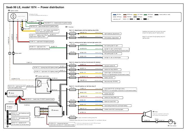
Saab 99 LE, model 1974 — Power distribution
20 Ignition switch
30 battery; 50 start;
15, 54 and X probably live with the key on.
contacts not drawn
30
X
50
1
54bf GN 0.75 → gear indicator light 91 (ignition sheet)
75 RD 1.0
4e GR 1.5
5 BR/VT 0.75
F1 · 8 A
F2 · 8 A
58 ign. switch
4.0
checked on the car
F6 · 8 A
F7 · 8 A
21 Ignition switch relay
86
F8 · 8 A
30/51
F9 · 8 A
1 RD 16.0
74e GR 6.0
234 RD 2.5 → master relay 101:30/51 (injection sheet)
F10 · 8 A
Relay 21's coil earths through lighting relay 8:31
(lighting sheet).
54 GN 0.75
(lighting sheet)
57 BL 0.75
(lighting sheet)
53 BL 0.75
(lighting sheet)
→ front parking light 13, right
→ tail light 14, right, via 58 tail lights;
59 GN on to the panel lighting (instruments sheet)
→ front parking light 13, left
→ tail light 14, left, via 58 tail lights
28 RD 1.0
(signals sheet)
36 GR 1.5
(climate sheet)
64 GL 1.0
(interior sheet)
21 RD/VT 1.0
(signals sheet)
185 GR 1.5
(injection sheet)
→ stop light contact 29
→ radiator fan relay 38:30/51
→ interior lights, via 58 interior feed;
80 BL on to cigarette lighter 48 (instruments sheet)
→ flasher unit 23:X
→ fuel pump relay 102:30/51
F11 · 8 A
49 SV 1.0
D−
−
B+
D−
73 GL 1.0
DF
DF
(wipers sheet)
89 GL 0.75
(wipers sheet)
148 RD 0.75
(climate sheet)
20 BL 2.5
(climate sheet)
93 GL 1.0
(interior sheet)
95e VT 1.0
(ignition sheet)
2 Alternator
→ wiper switch 61:54, via 58 wiper switch;
32 RD/VT on to combination instrument 47:2 (instruments sheet)
→ washer motor 63
→ radiator fan relay 38:86, coil
→ seat heating element 64, via 58 seat heating
→ inhibitor switch 90:2, reversing lights
40 Horn
67 RD 1.0
72 RD 1.0
D+
14 BR 1.0
→ heater fan switch 35:4
74 GR 6.0
38 SV 1.5 ← radiator fan 37,
via 59 radiator fan (climate sheet)
(lighting sheet)
92 VT 4.0
30
45 SV 1.0 ← left headlamp earth
(lighting sheet)
→ left headlamp, dipped beam
Headlamp main beams are not fused: they come
straight from lighting relay 8:F (lighting sheet).
Bar 9–11 · live with ignition on, fed from relay 21
4 Starter
46 SV 1.0 ← right headlamp earth
(lighting sheet)
58 GN 0.75
91 GR 4.0
85
87
12 V 60 Ah
(lighting sheet)
76 GR 1.0
76 GR 1.0 → light switch 10:4 (lighting sheet)
90 SV 0.75
44a GR 1.0
→ right headlamp, dipped beam
142 GR 1.5
142 GR 1.5 → lighting relay 8:30 (lighting sheet)
90 SV 0.75 → lighting relay 8:31,
then earth (lighting sheet)
(lighting sheet)
Bar 5–8 · always live, fed from the alternator B+ (battery)
F5 · 8 A
5e BR/VT 0.75
44b GL 1.5
50 GN 1.0
4 GR 1.5
battery − strap
2.5
Bar 3–4 · parking and tail lights, fed from light switch 10:5
F4 · 8 A
1 Battery
1.5
Bar 1–2 · dipped beams, fed from lighting relay 8:56a
44 GR 1.5
44 GR 1.5 ← lighting relay 8:56a,
dipped beams (lighting sheet)
50 GN 1.0 ← light switch 10:5,
parking and tail lights (lighting sheet)
+
0.75
traced (cable no. read)
22 Fuse box
F3 · 8 A
16, 50: ignition sheet
VT White
58 ign. switch
75 RD 1.0 → light switch 10:8 (lighting sheet)
4
GN Green
SV Black
118e GN/VT 1.0 → joint by the coil, rev counter (ignition sheet)
84e GL 1.5 → start inhibitor relay 89:30/51,
via 57 starter line (ignition sheet)
3
GL Yellow
RD Red
58 ign. switch
118 GN/VT 1.0
2
BR Brown
GR Grey
cable size, mm²:
15
84 GL 1.5
54
BL Blue
Single horn, switched to earth by the
horn contact in the steering wheel.
D+
F12 · 8 A
3 Voltage regulator
spare: connected to nothing; probably the empty holder on this car
58 horn
Headlamp wipers (their own 3 A fuse, fed from bar 9–11): not fitted on this car.
61 RD 0.75 ← charge warning lamp,
combination instrument 47:1 (instruments sheet)
On this car a relay has been cut into 61 RD (not drawn);
what it switches is still to be checked.
70 SV 1.0
71 SV 1.0
41 Horn contact
Page 2
Saab 99 LE, model 1974 — Ignition and starting
91 Gear indicator light
54bf GN 0.75
181 GN/VT 0.75 → master relay 101:86, coil (injection sheet)
7 Distributor
5 Ignition coil
6 Ballast resistor
54bf GN 0.75 ← ignition switch 20:15 (power sheet)
lit with the ignition on
119 SV 1.0
118e GN/VT 1.0
118e GN/VT 1.0 ← ignition switch 20:15, via 58 ign. switch (power sheet)
15
Rev counter: aftermarket, in the dashboard where the clock was (check D1), wired in series with the coil’s feed.
The ignition feed 118e, 181 and 195g meet at a joint by the coil; the rev counter’s black lead takes the current
to the meter and its brown lead brings it back to the resistor, the only lead on that end. If a lead comes off with
the engine running, it stops; while cranking, 119e still feeds the coil straight from the starter.
rev counter
1
195g GN/VT 0.75
7 BR/VT 1.0
The distributor’s contact breaker points switch the coil’s terminal 1 to earth. The injection’s
trigger contacts are in the distributor too (injection sheet).
Switch 90 is drawn in P: start contact closed, reversing contact open (it closes in R).
Switch 90’s wires: check E2.
Seat-belt warning contact 88 on the gear selector: probably not fitted
(it goes with a belt warning lamp).
Ballast resistor 6 lowers the coil’s voltage while the engine runs. While cranking, starter
terminal 16 feeds the coil’s side of it directly (119e SV 1.0), so the coil gets full voltage for
90 Start inhibitor
starting.
1
95e VT 1.0
2
95e VT 1.0 ← fuse 11 (power sheet)
and reversing
light switch
4
95f VT 1.0 → reversing lights, via 60 inhibitor reversing (signals sheet)
3
Relay 89 and switch 90 let the starter turn only in P or N: with the ignition on, switch 90’s start
195h GL 0.75
195f RD 0.75
85
86
330 SV 0.75
contact (closed in P and N) energises relay 89, which joins 84a GL 1.5 to 84b GL 1.5 and so
closes the starter line.
60 inhibitor start
89
Start inhibitor relay
30/51
84a GL 1.5
84b GL 1.5
87
Relay 89 is drawn as the factory wired the 1974 automatic. This car is a 1973 chassis, so
whether it has relay 89 is check F1. A car without the relay has a short jumper (84c GL 1.5)
119e SV 1.0
across the two pins of 57 starter line; a 1973 automatic may run the starter line through switch 90
57 starter line
60 starter signal
probably on to 59 cold start: start signal
218 GL 0.75 and cold-start valve 231 GL 0.75
(injection sheet; check E1)
itself instead.
84h GL 0.75
84e GL 1.5
84e GL 1.5 ← ignition switch 20:50, via 58 ign. switch (power sheet)
16
4 Starter
84f GL 1.5
50
30
30: battery +, alternator, master relay
(power sheet)
BL Blue
BR Brown
GL Yellow
GN Green
traced (cable no. read)
GR Grey
RD Red
SV Black
VT White
ends on diagram
4.0
checked on the car
cable size, mm²:
0.75
1.5
2.5
HT lead (no number)
A cable is labelled with its colour and size (7 BR/VT 1.0),
a part with its name (7 Distributor).
Thin black lines without a label: leads with no cable number.
Page 3
Saab 99 LE, model 1974 — Fuel injection (D-Jetronic)
229 SV 0.75
228 SV 0.75
226 SV 0.75
227 SV 0.75
92 Control unit
Cables 201–224 each run to the pin with the same last two digits (201 to pin 1, 224 to pin 24).
Pins 2 and 25 are not used.
93
Injectors
cylinder 2
cylinder 1
cylinder 3
earth
point
cylinder 4
1
2
3
4
5
6
7
8
9
10
11
12
13
14
15
16
17
18
19
20
21
22
23
24
25
203 RD/VT 0.75
204 GN/VT 0.75
205 BL/VT 0.75
206 BR/VT 0.75
211 SV 0.75
209 GL 0.75
98 Trigger contacts
220 BR 0.75
235 SV 0.75
214 RD 0.75
222 RD 0.75
22
212 BL 0.75
12
221 GN 0.75
21
217 VT 0.75
213 BR 0.75
acceleration
contacts
1
14
full load
13
7
95 Temperature
sensor I
8
10
223 GL 0.75
215 GN 0.75
210 VT 0.75
208 BR 0.75
201 BL 0.75
20
47
207 RD 0.75
9
97 Temperature
sensor II
coolant
15
96 Pressure sensor
C°
intake air
idle
in the distributor (ignition sheet)
17
94 Throttle switch
219 SV 0.75
218 GL 0.75
216 GR 0.75
232 SV 0.75
187 SV 1.5
224 GR 0.75
102 Fuel pump relay
101 Master relay
85
234 RD 2.5
87
186 GR 1.5
30/51
234 RD 2.5 ← starter 30, battery + (power sheet)
87
103 Fuel pump
in the boot, left
181 GN/VT 0.75 ← ignition feed joint
by the coil (ignition sheet)
181 GN/VT 0.75
230 GR 0.75
86
86
30/51
185 GR 1.5
185 GR 1.5 ← fuse 8 (power sheet)
85
182 SV 0.75
BL Blue
BR Brown
GL Yellow
GN Green
GR Grey
RD Red
SV Black
VT White
cable size, mm²:
0.75
1.5
2.5
4.0
The master relay switches on with the ignition (181) and feeds the control unit (216, 224)
C°
pin 1
231 GL 0.75
233 BL 0.75
and the pump relay’s coil; the control unit runs the pump through the pump relay (219).
The cold-start valve gets current only while the starter turns (starter line, 231),
through its thermostat contact, which opens when warm.
pin 2
59 cold start
99 Cold-start valve
59 cold start: where on the starter line it sits is still to be checked (check E1).
traced (cable no. read)
grey inside a part: probably
Throttle switch: the full-load contact (14) probably closes only near full throttle.
Terminal marks in light grey: probably. Cylinder numbers: probably.
← starter line, live only while cranking: probably joins
at 60 starter signal (ignition sheet; check E1)
100 Thermostat contact
Page 4
Saab 99 LE, model 1974 — Lighting circuit
FRONT
58 GN 0.75
car’s right side at top
58 GN 0.75 ← fuse 3 (power sheet)
REAR
4-door saloon (this car)
13 Parking light R
75 RD 1.0 ← ignition switch 20:X (power sheet)
28 indicator, 23be RD/VT: signals sheet
Rear lamp block R
earth: probably through the housing
28 indicator
25b RD/VT: signals sheet
10 Light switch
8
54b GN 0.75
off · parking (4–5) ·
3
46 SV 1.0
46 SV 1.0 → battery − strap,
earth (power sheet)
14 tail
headlamps (4–5 and 8–3): probably
28f RD: signals sheet
30 stop
98 VT: signals sheet
32 reversing
4
5
44b GL 1.5
56b GN 0.75
15 number plate
44b GL 1.5 ← fuse 1 (power sheet)
earth: probably through the housing
41 BL/VT 0.75 → main-beam indicator,
combination instrument 47:7
(instruments sheet)
11/12 Headlamp R
42a BL 1.5
upper 11 main, lower 12 dipped
50 GN 1.0 → bar 3–4: fuses 3 and 4 (power sheet)
76 GR 1.0 ← bar 5–8, always live (power sheet)
8 Lighting relay
59 GN 0.75 → rheostat 16,
panel lighting (instruments sheet)
F
56a
39 GL 0.75
42b VT 1.0
44 GR 1.5 → bar 1–2:
fuses 1 and 2 (power sheet)
3
142 GR 1.5 ← bar 5–8,
always live (power sheet)
30
2
1
54 GN 0.75 ← fuse 3 (power sheet)
53 BL 0.75 ← fuse 4 (power sheet)
54 GN 0.75
1
53 BL 0.75
2
86
58 tail lights
11/12 Headlamp L
31
147 SV 0.75
141 VT 0.75
S
90 SV 0.75 ← ignition switch relay 21:85,
its coil (power sheet)
8:31 to the headlamp wipers: not fitted on this car
58 dimmer
upper 11 main, lower 12 dipped
141e VT 0.75
45 SV 1.0
44a GR 1.0
LH
44a GR 1.0 ← fuse 2 (power sheet)
8 Lighting relay: what it does
drawn at rest: lights off, stalk released
state
coils
path (each starts at terminal 30)
lights
lights off
–
30 → 1’s contact (up) → 2’s contact: open
nothing
flash, lights off
2
30 → 1’s contact (up) → 2’s contact → F
main beams
headlamps on
1
30 → 1’s contact (down) → 3 → 56a or F
dipped or main
headlamps on, stalk pulled
1, 2
2 moves 3 over (56a ↔ F); it stays
dipped ↔ main
Rear lamp block L
55a BL 0.75
15 number plate
97/98 VT: signals sheet
Every pull of the stalk moves 3 over, a flash with the lights off too, and 3 stays there until the next pull.
9 Dimmer/flasher stalk
28e/28f RD: signals sheet
32 reversing
30 stop
pull: earths S (main/dipped, or flash)
53a BL 0.75
45 SV 1.0 → battery − strap,
earth (power sheet)
14 tail
25a BL/VT: signals sheet
57 BL 0.75
27 indicator
57 BL 0.75 ← fuse 4 (power sheet)
earth: probably through the housing
13 Parking light L
27 indicator, 23a BL/VT: signals sheet
earth: probably through the housing
Cable key: number · colour · mm²
cable size, mm²:
0.75
1.5
BL Blue
BR Brown
GL Yellow
GN Green
traced (cable no. read)
GR Grey
RD Red
SV Black
VT White
ends on diagram
faded blade: its other position
coil to the contacts it moves
Main beams come straight from relay 8:F, not fused; dipped beams through fuses 1 and 2 (power sheet).
Relay 8 changes over between main and dipped each time stalk 9 earths its terminal S (headlamps on);
with the headlamps off, the same pull flashes the main beams.
The headlamps need the ignition on (light switch 10:8 is fed from ignition switch 20:X); parking and tail lights and the flash do not.
56b and 55a, from the number-plate lights, end on the diagram: where they go is not known.
2.5
4.0
Page 5
Saab 99 LE, model 1974 — Instruments, warning lamps and panel lighting
31 SV 0.75
58 fuel gauge
44 Oil pressure contact
46 Fuel level
transmitter
B
59 fuel sender
30 BR 0.75
30e BR 0.75
30f BR 0.75
29 GR 0.75
29e GR 0.75
29f GR 0.75
W
G
B its earth, W the low-fuel
lamp’s lead, G the gauge’s
112 BL 1.0
P
47 Combination instrument
11
12
Clock removed: an aftermarket rev counter sits in its place, wired in series
with the coil’s feed at the ballast resistor (ignition sheet), with no feed or
earth of its own. The clock’s feed 13 BL 1.0 (from the lighter, live at all
times) and its earth 105 SV 0.75 are unused on the car and not drawn (check D1).
3
48 Cigarette lighter (with lamp)
45 Temperature transmitter
its lamp’s own wiring is not shown
130 GL 1.0
80 BL 1.0
9
C°
oil
temperature
61 RD 0.75
fuel
gauge
1
16 Rheostat switch, panel illumination
brake
charge
On this car a relay has been cut into 61 RD between
the alternator and this lamp (not drawn); what it
switches is still to be checked.
19 Glove compartment and heater control light
102 GN 0.75
61 RD 0.75 → alternator D+ (power sheet)
80 BL 1.0 ← fuse 7, via 58 interior feed (interior sheet)
B
low fuel
106 SV 0.75
C°
main
beam
59 GN 0.75
18
indicator
101 GN 0.75
18
133 GN 0.75
17 Switch light
32 RD/VT 0.75 ← fuse 9, via 58 wiper
switch pin 1 (wipers sheet)
136 SV 0.75
43 Handbrake contact
135 SV 0.75
107 SV 0.75
62 GN/VT 0.75
114e VT 0.75
4
109 SV 0.75
115 GL 0.75
58 brake warning
2
110 GN 0.75
108 SV 0.75
42 Brake warning contact
6
32 RD/VT 0.75
41 BL/VT 0.75
41 BL/VT 0.75 ← lighting relay 8:F,
main beams (lighting sheet)
5
114 VT 0.75
7
59 GN 0.75 ← fuse 3, via 58 tail lights (lighting sheet)
62 GN/VT 0.75 ← flasher unit 23:P (signals sheet)
dash earth
26 SV 1.0 ← hazard repeater 26 (signals sheet)
BL Blue
BR Brown
GL Yellow
GN Green
GR Grey
RD Red
SV Black
VT White
cable size, mm²:
0.75
1.5
2.5
4.0
Inside 47 (its own terminal numbers): a + rail from 2 feeds both gauges and the oil (11), fuel warning (12), brake (5) and charge (1) lamps; an earth rail to 4 takes the gauges’ other leads
and the main-beam (7) and indicator (6) lamps. The leads from 9 into the temperature gauge and from 1 into the charge lamp are grey: probably.
Supply: 32 RD/VT from fuse 9, shared with the wiper feed at 58 wiper switch, pin 1. Instrument earth (47:4) goes through the lighter body (109 SV) and on by 108 SV to the dash earth.
Brake lamp (47:5): brake warning contact 42 and handbrake contact 43 are in parallel on it, either earths it; 115 GL probably joins 114 VT on the instrument side of 58 brake warning.
Contacts as drawn: brake warning contact 42 open; handbrake contact 43 closed (plunger out: handbrake on, probably).
traced (cable no. read)
Panel lighting (lit with the tail lights from fuse 3, dimmed by rheostat 16): 101 GN feeds switch light 17 and, by 110 and 133 GN, the two panel lights 18;
grey inside a part: probably
102 GN feeds glove compartment light 19. The panel lights earth at switch light 17’s earth side and on by 107 SV; light 19 earths by 106 SV through the lighter.
Choke warning lamp and choke contact: probably not fitted on this injection car (injection cars have a spare switch where the choke control would be); their feed 146 BR would leave pin 1 of 58 wiper switch (wipers sheet).
18 Instrument panel
lights (two)
Page 6
Saab 99 LE, model 1974 — Indicators, hazards, brake and reversing lights
FRONT
Indicators and hazards
Rear lamp block, R
car’s right side at top
62 GN/VT 0.75 → indicator repeater,
combination instrument 47:6 (instruments sheet)
13/28 Front lamp housing, R
26 SV 1.0
21 RD/VT 1.0 ← fuse 8 (power sheet)
28 indicator
54b GN:
lighting sheet
26 SV 1.0 → dash earth
(instruments sheet)
58 GN: lighting sheet
14 tail
21 RD/VT 1.0
30 stop
23 Flasher unit
13 parking light, 28 indicator
earth: probably through the housing
32 reversing
26 Hazard repeater lamp
56b GN:
lighting sheet
X
23be RD/VT 1.0
24 Indicator switch
earth: probably through the housing
P
22 GN 1.0
+
22e GN 1.0
R
24be RD/VT 1.0
L
24ae BL/VT 1.0
15 number plate
54
L
R
L
59 indicators
24a BL/VT 1.0
24b RD/VT 1.0
25 Hazard warning switch
28f RD 0.75
57 front
indicator R
1
REAR
2
car’s right side at top
25b RD/VT 1.0
23b RD/VT 1.0
23a BL/VT 1.0
60 inhibitor
reversing
95f VT 1.0 ← inhibitor switch 90:4,
closed in R (ignition sheet)
BL Blue
BR Brown
GL Yellow
GN Green
GR Grey
RD Red
SV Black
VT White
0.75
1.5
2.5
60 reversing
link
58 reversing
95 VT 1.0
96 VT 1.0
Rear lamp block, L
4.0
97 VT 1.0
cable size, mm²:
95f VT 1.0
traced (cable no. read)
13/27 Front lamp housing, L
57 BL: lighting sheet
13 parking light, 27 indicator
earth: probably through the housing
98 VT 0.75
Brake and reversing lights
Flasher 23 is fed on X from fuse 8 (21 RD/VT; always-live bar 5–8). Its L output, 22 GN, passes through hazard switch 25’s +
terminal to indicator switch 24’s 54 (22e GN); the stalk sends it on R (24b) or L (24a), through 59 indicators, to that side’s front and
rear indicators.
The flasher’s P terminal lights the indicator repeater in the instrument.
Switches are drawn at rest: 24 centre-off; 25 off, its bar touching none of its contacts. Pressed, 25’s bar probably joins the lamp
contact, +, R and L (the dotted marks), so the flasher feeds both sides and repeater lamp 26.
Repeater lamp 26 sits in hazard switch 25. Its earth side also takes 105 SV, the clock’s earth; the clock has been removed (rev
counter instead, check D1) and 105 is unused, so it is not drawn.
Stop light contact 29 closes when the brake pedal is pressed.
Reversing lights: switched by the gear selector’s inhibitor switch 90, closed in R (ignition sheet); on a manual-gearbox car a
reversing light switch takes the place of 60 reversing link.
Lamp housings and rear lamp blocks: no earth lead is drawn; each probably earths through its housing. The parking, tail and
number-plate bulbs are wired on the lighting sheet (open terminals here). In each rear block, tail light 14 and number-plate light 15
are joined inside the block; the link hops over the stop and reversing leads without joining them.
55a BL:
lighting sheet
32 reversing
29 Stop light contact
28 RD 1.0 ← fuse 5 (power sheet)
28 RD 1.0
15 number plate
28g RD 1.0
28e RD 1.0
30 stop
60 stop lights
53a BL:
lighting sheet
14 tail
27 indicator
earth: probably through the housing
25a BL/VT 1.0
Page 7
Saab 99 LE, model 1974 — Wipers and washers
32 RD/VT 0.75 → combination instrument 47:2,
its supply (instruments sheet)
choke warning lamp’s feed 146 BR:
probably not fitted (instruments sheet)
62 Two-speed wiper motor
14 BR 1.0 ← fuse 9 (power sheet)
61 Wiper switch
14e BR 1.0
1
54
3
16 GN 1.0
16e GN 1.0
31b
53b
2
slow
5
M
15 RD 1.0
15e RD 1.0
53
3
fas
t+
wa
she
r
fast
4
17 GR 1.0
17e GR 1.0
53a
4
S
washer
1
18 BL 1.0
18e BL 1.0
S: not used (headlamp wipers not fitted)
5
88e SV 0.75
2
6
175 SV 1.0
58 wiper switch
89 GL 0.75 ← fuse 9
(power sheet)
the same earth point as the heater fan motor’s
138 SV (climate sheet)
63 Washer motor
88 SV 0.75
BL Blue
BR Brown
GL Yellow
GN Green
GR Grey
RD Red
SV Black
VT White
cable size, mm²:
0.75
1.5
2.5
4.0
Fuse 9 (ignition on) feeds the wipers through 14 BR to 58 wiper switch, pin 1 (pins numbered from the top: our count), and the washer motor through 89 GL. The washer motor is switched to earth by the wiper switch: 88 SV, pin 6, 88e SV.
Wiper motor 62: 16 GN on 3 feeds the fast brush and 15 RD on 5 the slow one; the third brush is on the housing, earthed by 175 SV. The bar from M to the housing’s corner is probably the drive, not a wire.
Parking: the motor’s change-over 2, joined to 5 outside the motor, rests on 1 (18 BL to the switch’s 31b) and swings to 4 (17 GR to 53a). Switched off, 61 feeds 53a and earths 31b, so away from park the motor probably runs on slow through 4, and at park 1 earths the slow brush
and brakes it.
Switch 61 is drawn at rest (off): its lever joins 54 to 53a and the earthed pivot to 31b. Grey dashed lines: its other positions, probably slow (54 to 53), fast (54 to 53b) and fast with the washer (54 to the upper 53b finger, and the washer terminal earthed).
traced (cable no. read)
61’s washer terminal: its number is not known; ‘washer’ is our name for it. The contact tied to 61’s housing (earth) is not named.
grey inside a part: probably
18e BL runs under the switch and up its right side into 31b, crossing 88e SV.
switch position line (the lever’s other positions)
Headlamp wipers: not fitted on this car; switch 61’s S, which would switch their relay, has nothing on it.
Page 8
Saab 99 LE, model 1974 — Heater fan and radiator fan
20 BL 2.5
20 BL 2.5 ← fuse 10
(power sheet)
4
Radiator fan
Heater fan
38 Radiator fan relay
57 heater fan
59 radiator fan
37e SV 1.5
38e SV 1.5
87
pin 1
150 SV 1.0
37 Radiator fan motor
37 GN 1.5
pin 2
30/51
85
86
36 GR 1.5
148 RD 0.75
row 1
drawn off: the bar
touches no contact
148 RD 0.75 ← fuse 9
(power sheet)
series resistor (slow speed)
row 2
35 GR 1.0
row 3
138 SV 2.5
6
38 SV 1.5
39 Thermostat contact
C°
149 SV 0.75
open when cold, as drawn;
closes when the coolant is hot
36 Heater fan motor
BL Blue
BR Brown
GL Yellow
GN Green
Radiator fan: relay 38 (drawn at rest, contact open) takes its coil feed from fuse 9, live with the ignition on, and its contact feed from fuse 6, always live.
GR Grey
RD Red
SV Black
VT White
Thermostat contact 39 earths the coil when the coolant is hot, so the fan runs only with the ignition on. 37 GN becomes 37e SV beyond radiator fan connector 59,
0.75
8
35 Heater fan switch
38 SV 1.5 → battery − strap, earth
(power sheet)
cable size, mm²:
33 GL 2.5
+
36 GR 1.5 ← fuse 6
(power sheet)
1.5
2.5
4.0
so both of the motor’s own leads are black; its 38e side is earthed twice, by 38 SV to the battery − strap and by 150 SV to an earth of its own.
Heater fan: fuse 10, live with the ignition on, feeds switch 35. Probably position 1 is slow (4 to 6: 35 GR through the series resistor) and position 2 fast
traced (cable no. read)
(4 to 8 and 6: 33 GL straight to the motor). The series resistor has no number of its own; it sits on the motor side of heater fan connector 57, between rows 2 and 1.
short dashes inside a switch: its other positions
The motor returns through row 3 and 138 SV to the earth point it shares with the wiper motor.
grey dashes inside a relay: the coil moving its blade
Thin black lines without a label: leads with no cable number.
the same earth point as the wiper motor’s
175 SV (wipers sheet)
Page 9
Saab 99 LE, model 1974 — Interior lights and seat heating
Seat heating
Interior lights
Fed from fuse 7 (always live). Lamps 50, 51 and 52 return through dome light 50’s switch: on (to earth), off (as drawn) or door (to the door line).
Each door contact 54 and switch 53 earth that door line in parallel: an open door, or 53 closed, lights them while 50’s switch is at door.
58 seat heating
93f GL 0.75
56 Trunk light contact
55 Trunk light
94 SV 1.0
93e GL 1.0
93 GL 1.0 ← fuse 11 (power sheet)
60 seat feed
59 seat heater
123 BL 0.75
80 BL 1.0 → cigarette lighter 48
(instruments sheet)
at the left hinge; switches 55 on its earth side
65 GL 0.75
64 GL 1.0 ← fuse 7 (power sheet)
51 Dome light, forward (at the mirror)
same earth point as
120 SV 0.75 from switch 53
64 Seat heating element with thermostat
66f SV 0.75
121 GR 0.75
58 interior feed
65f SV 0.75
C°
50 Dome light, middle
switch: on (earth) / off (as drawn) / door
Fed with the ignition on (fuse 11). The thermostat is inside the
element, drawn closed (it is closed while cold, probably).
54 Door contacts
65e GL 0.75
Which seat or seats it heats, and whether there is a switch: check I2.
66be SV 0.75
52 Ignition switch light
66g SV 0.75
66e BL 0.75
66ae SV 0.75
66 SV 0.75
60 interior switch
122b SV 0.75
53 Interior lighting switch
122 SV 0.75
120 SV 0.75
58 door contacts
122a SV 0.75
which two are the
rear doors: check I1
same earth point as 94 SV 1.0
(seat heating)
BL Blue
BR Brown
GL Yellow
GN Green
The door line is one line: 66be, 66ae and 66g SV 0.75 from dome light 50; 66 and 122 SV 0.75 on switch 53’s pivot; 122b and 122a SV 0.75 beyond 58 door contacts.
GR Grey
RD Red
SV Black
VT White
Door contacts 54 and trunk light contact 56 are drawn closed: plunger out, with the door or lid open (probably).
Which two door contacts are the rear doors is still to be checked (check I1).
cable size, mm²:
0.75
traced (cable no. read)
1.5
2.5
4.0
64 GL 1.0 (fuse 7 to the interior lights) is a cable, not part 64, the seat heating element.
Seat heating: its return 94 SV 1.0 is drawn to an earth of its own here, but it shares one earth point with 120 SV 0.75 from switch 53.
Thin black lines without a label: leads with no cable number.