text of this document (ocr, may contain errors)
Page 1
Water injection
Wassereinspritzung
Group 14:3/1
Sep 1988
Pos ArtNo. Description Bezeichnung Model
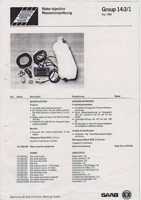
WATER INJECTION WASSEREINSPRITZUNG
Features Produkteigenschaften
@ Complete water-injection tuning kit. © Kompletter Tuningsatz in Form von Wassere-
© By injecting water into the intake manifold, inspritzung.
the boost pressure is raised from 0.7 to 1.2 © Durch Wassereinspritzung im Ansaugrohr
bar. wird der Ladedruck von 0,7 auf 1,2 bar
© Engine output increase: from 145 to at least erhoht.
160 bhp. © Leistungserhohung: von 145 auf min. 160
@ If fitted to the Saab 99, the wiring and hoses PS.
must be modified. © Bei Montage im Saab 99 missen Kabelnetz
und Schlauche modifiziert werden.
Benefits .
© Improves the overall performance of the Vorteile fir den Kunden
engine. @ Verbessert das Gesamtleistungsvermogen
Fitting time (Saab 900): 2,3 hours eau
Country of manufacture: Sweden Montagezeit (Saab 900): 2,3 Stunden
Hergestelit in Schweden
137000006 Water injection equipment Wassereinspritzung Saab Turbo M78-80
SPARES ERSATZTEILE
137000014 One control valve Steuerventil, 1 St.
137000022 One diode assembly Diode, komplett, 1 St.
137000030 One level transmitter Niveaugeber, 1 St.
137000048 One bulb Glahlampe, 1 St.
137000055 One pressure sensor, 1.35 (Orange) Drucksensor 1,35 (Orange), 1 St.
137000063 One pressure sensor, 0.7 (Red) Drucksensor 0,7 (Rot), 1 St.
137000071 One pressure sensor, 0.3 (Black) Drucksensor 0,3 (Schwarz), 1 St.
137000089 One time-delay relay Zeitrelais, 1 St.
137000097 One safety valve Sicherheitsventil, 1 St.
137000105 One rubber bush (intake manifold) Gummibuchse (Ansaugrohr), 1 St.
(10) 93 24.021 Two rubber bushes (by-pass)
(10) 85 73669 One delivery valve
Saab-Scania AB, Saab Car Division, Nykoping, Sweden
Gummibuchse (By-pass), 2 St.
Druckventil, 1 St.
sans ©)
Page 2
Note
| countries with a very warm climate like The Middle East, Australien etc, is it necessary
to install the Regulator Box between the wheel housing plate and the front fender (in front
of the water container).
- Disconnect left parking light
= Loosen the bracket from the regulator box
- Exchange the hose between the safety valve and the regulator box (length 800 mm)
- Exchange the hose between the pressure valve and the regulator box (length 700 mm)
Note! The hoses cannot be joined
_ Mark the positions for the holes and drill g#8 6 mm holes in the front member (see
drawing)
= Locate the regulatorbox with a strap
- Check the drawing of the hoses as wrinkles must be avoided
Material
1—Hose (10) 8560732 length 1500 mm
A, \-Strape (10) 7971906 Seog
Page 3
@ SAAB -SCANIA . FITTING INSTRUCTION
F Saab Personbisdvisionen Artikelnr 653162
U : Datum Urobve Side
May 1981 1 1
Merke/Modell TAramodel! Produkt
Saab 900 Turbo 1979-80 Water injection (sport kit)
Saab 99 Turbo 1978—80 Artikeinr
24455
Included items
1 Regulator box with hoses 8 Cable harness, level warning lamp 14 Clips quant. 1
2 Safety valve 9 Level warning lamp with holder 15 Self tapping screw quant. 2
3 Water container with pump 10 Pressure valve 16 Self tapping screw quant.1
4 Cover 11 T-junction 17 Strap quant. 2
5 Filter 12 Rubber bush = quant. 2 18 Warning label
6 Pressure monitor (1,3 bar) 13 Rubber bush = quant. 1 19 Emblem
7 Cable harness complete
1 Move the electronic ignition box
— Diep ground connection from battery
— Repfove L.H. indicator lamp assembly
Move the elgetfonic ignition box forwards:
ck edge of the box in the holes previous-
Mark the positions of fixing holes in the @@y
inner wheel house behind the L.H. head lamp
— Drill 2 holes 6 mm dia (N.B. takes care pp
cables, hoses, etc.)
4
ES
2
8
— Lead the wing c. and pipe to the water con-
tainer @ and’connect to the relevant connections
a“
— Fasten the water co! er by threading the strap
through an existifig hole in the wheel housing and
tighten aroUnd the neck of the water container
a
Page 4
4 Fit the safety valve and pressure v:
f oles for safety and pres-
e figure (mark so that the
itioned straight between the pipes
— Mark the positions of
sure valves as sho
safety valve is
ay
when moun:
— Remove the pressure, suction pipes
a
before refittin,
a
— Pust; i+ rubber bu
— Fit the suction pipe,
Page 5
t %.
T
22
5 Lo j
Fuse box Time relay Pressure Pressure Level monitor |
ss ore az sensor sensor |
=| jl ae
a ® | 37 31) |
uo : ;
| a |
xX
Control valve
e
6 Fit level warning lamp
— Remove the lower ‘of the instrument panel
— Fit the warning! to the instrument panel
— Connect the pe re to chassis H”
— Connect the green wire e centre connector block
(red) No. 21 for ugh feed to fuse panel
7 Exchange turbo pressure moni
Pressure monitor for the one in
— Exchange the existi
— Inthe summer nosmat fap water can be used
— In the wip for sub-zero temperatu-
res exi§t, Methylated spirit,
jhen-a=
WARNING! Do not use regular anti-freeze, ethylen /
glycol or windscreen washer addative as an anti-
freeze, as these can damage the motor severely. Take
care to ensure a high di of cleanliness when fill-
ing the containe:
~ sigs ai warning label onto the water con-
iner
5
ES Level warning
lamp switch
©) Level warning
lamp Z
denatured wood alcohol)
must be mixed with the water to avoid freezing
Mixing table
Temp °C Volyme of
Meths.
AL
15L
2L
2.5L
3L
Page 6
9 Increase charge pressure
— Open the cover to the char: essure regulator
membrane and tension thespring (basic setting:
screw in the large ai undo. one turn)
sO that the chargiffg pressure rises to 1.15—1,20 bar.
See workshop’ manual, section 291.
— While adjusting the charging pressure by trial and
error, note if the motor “pinks” and check that the
water injection is working. If pinking occurs at
charging pressures up to 1.20 bar:
— check water injection
1. Start the motor and leave ticking over.
2. Remove the hose from the pressure sensor at the
T-piece (7) and connect instrument 8392813,
together with a suitable pump, (eg: radiator tester)
to the hose.
3. Raise the pressure, using the radiator tester, and
check that the water injection system starts work-
ing at approx. 0.7 bar.
4. Water consumption should be 150 ml/minute.
ES — If the system does not work, check that all con-
nections are correctly made.
Fit the “s'-emblem
(loosen the 9
the left)
e right of the trunk door
rbo’’-emblem and move it a bit to
The injection equipment has its own safe-guard which
operates if the water pressure falls below approx. 0,3 bar.
eg, when:
— The water container is empty
— the injection jet is blocked
— the pump has seized or is without power
In such a case the charging pressure is automatically low-
ered to an acceptable level.
ates NEN
If the injection jet (8) is only partly blocked, the safe-guard is
not triggered, but the motor starts pinking under load.
Clean the jet (8) before loading the motor heavily again, so
that sufficient water is obtained. If the water in the con-
tainer drops below a certain level the warning lamp will
light.
tA
. 6
COGS /
CAN AGTAHWN
Leave this fitting instruction in the car after fitting!
9 (\s
Regulation unit
A Control valve
B Pressure sensor 0,7 bar
C Pressure sensor 0,3 bar
Water container
Water pump
Check valve
Pressure valve
Safety valve
T-piece
Calibrated jet
Filter