text of this document (ocr, may contain errors)
Page 1
me TEVES
1993 Saab 900
DESCRIPTION
Saab Mark tl Anti-Lock Brake (ABS) system monitors front wheels individ-
ually, and rear wheels as a pair. The ABS system consists of 4 wheel sen-
sors, felays, fuses, hydraulic unit, warning lights, and an Electronic Con-
trol Unit (ECU). Brake servo unit is hydraulically operated. ECU provides
selt-diagnostic capability.
OPERATION
Each time a sensor rotor tooth passes by the wheel speed sensor, a mag-
netic field is distoried, causing an electric signal to be generated. These
signals, which are proportional io. wheel speed, are transmitted to the
Electronic Contral Unit (ECU), ECU processes these signals and com-
putes a value defined as reference speed, See Fig, 7.
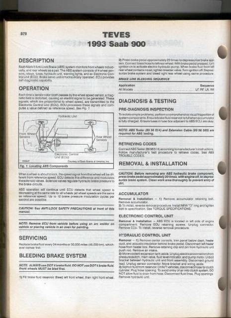
Hydraulic Unit
Rear Wheel
Sensors
Electronic Control
Unit (ECU)
Courtesy of Saab-Scania of Amorica, inc
100547
Fig. 1: Locating ABS Components
When awheel is about to lock, the speed signal from that wheel will be dif-
ferent trom reference speed. ECU detects this difference and modulaies
the solenoid valves. Solenoid valves regulate hydraulic brake pressure to
the brake circuits.
ASS operation will continue until ECU detects that wheel speed is
decreasing at tnesame rate for all wheels (all wheel speeds are the same
as reference speed), Up to 12 brake pressure modulation cycles per
second are possible.
CAUTION: See ANTI-LOCK SAFETY PRECAUTIONS at front of this
manual,
NOTE: Remove ECU from vehicle before using an arc welder on
vehicle or piacing vehicle in an oven for painting.
SERVICING
Replace brake fluid every 24 months or 30,000 miles (48,000 km), which-
ever comes first.
BLEEDING BRAKE SYSTEM
NOTE: ALWAYS use DOT 4 brake fluid. DO NOT uss DOTS brake fluid.
Front wheels MUST be bled first.
1) Fill brake fluid reservoir. Bleed left front wheel, then right front wheel.
2) Press brake pedal approximately 20 times to depressurize brake sys*
tem. Connect bleed hose to teftrear wheel, With brake pedal pressed, turn
ignition on to activate electric hydraulic pump. When brake fluid from tet
rear wheel contains no air, tighten bieeder valve. Turn ignition off, Depres:
surize brake system and bleed right rear wheel using same procedure.
BRAKE LINE BLEEDING SEQUENCE
Application Sequence
Pa INEMONE icia's arenstale srdiatn ax alere aid-s¢ orale baal hove vie oes LF. RF. LA, RA
DIAGNOSIS & TESTING
PRE-DIAGNOSIS INSPECTION
To isolate simple problems, perform a comprehensive visual inspection ot
ayatem components. Ensure brake fluid reservoiris full when accumulator
is fully Charged. Ensure tuses in fuse box adjacent to ABS ECU are okay
NOTE: ABS Tester (89 96 $14) and Extension Cable (89 96 589) are
required for ABS testing.
RETRIEVING CODES
ConnectABS Tester (89 9651 4) according to manufacturer's instructions
Follow manufacturer's test procedure to retrieve codes. Sea ABS
TROUBLE CODES.
REMOVAL & INSTALLATION
CAUTION: Before removing any ABS hydraulic brake component,
press brake pedal approximately 20 times, with engine off, to depres-
surize brake system. Clean work erea thoroughly to prevent entry of
dirt.
ACCUMULATOR
Removal & Installation — 1) Remove accurnulator retaining boll
Remove accumulator.
2) To install, reverse removal procedure. install NEW "O" ring and tighten
boil to specification. See TORQUE SPECIFICATIONS,
ELECTRONIC CONTROL UNIT
Removal & Installation — ABS ECU is locatad in left side of engine
compartment. Remove ECU retaining screws. Unplug connector
Remove ECU. To install, reverse removal procedure.
HYDRAULIC CONTROL UNIT
Removal — 1) Remove center console, trim panel below dash, heater
duct, and acoustic insulation behind brake pedal. Disconnect left heater
hose from heater box, Remove retaining clip and pin from hydrauli¢ unit
push fod, Remove air intake.
2) Move coolant expansion tank aside, Unplug electrical connectors from
pressure switch, main valve, fluid level indicator, and pump motor. Unbolt
bracket between hydraulic unit and front assembly. Disconnect ground
lead. Unpiug sensor connector. Move bracket and wiring aside.
3) Siphon fluid from reservoir. On M/T vehicles, disconnect hose forclutch
cylinder. Plug hose opening. To avoid entry of air into clutch system, DO
NOT allow fluid to drain from hose, Disconnect fivid lines. Plug openings.
Remove hydraulic unit.