text of this document (ocr, may contain errors)
Page 1
K369
SERVICE KIT INSTRUCTIONS
Lucas Girling Limited, Parts & Service, Birmingham Ro:
Girling
West Bromwich West Midlands B71 4JR: England.
eaning Fluid or unused Castrol/Girling Brake and Clutch
WARNING For cleaning brake parts use only Girling
ch Fluid in Girling Car Brake Systems and CRIMSON Fluid
Fluid. Use only Castrol/Girling Universal Brake and
in Girling Commercial Vehicle Systems.
os
: Lucas Girling recommend that for optimum results and safety, worn units should be replaced by new
units. If, however, it is decided to service a used component particular attention should be paid to the
following, but in any case of doubt replace the unit or seek professional advice.
M16 AH’ CALIPER
The Service Kit for M16AH type calipers has been divided, and the components/seals required to service the hydraulic
cylinder and the handbrake lever, are packed individually within the kit box.
4
The individual kits are easily recognised by virtue of their size and type of grease content.
A. Hydraulic kit contains 16 items and rubber grease.
B. Handbrake lever kit contains 6 items and G.R.C Grease.
IMPORTANT: DO NOT USE EITHER TYPE OF GREASE OTHER THAN WHERE SPECIFIED IN THE FITTING
INSTRUCTION.
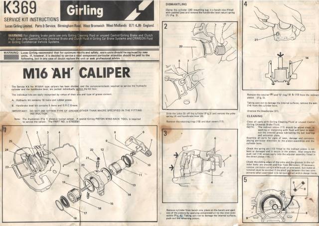
Note: The illustration (Fig 1) shows a typical caliper. A special Girling PISTON WIND-BACK TOOL is required
to service the caliper. The PART NO. is 67932001.
17
DISMANTLING
Clamp the cylinder (20) mounting lugs in a bench vice (fitted
with padded jaws and remove the handbrake lever return spring
(7) (Fig. 2).
2
Slide the yoke (5) off the cylinder (Fig.3) and remove the yoke
spring (4) and handbrake lever (6).
Remove the retaining rings (18) and dust covers (17).
Remove the retainer'(8) and ‘O’ ring (9) & (10) from the indirect
piston (Fig. 5).
Taking care not to damage the internal surfaces, remove the seals
(14) from the cylinder bore.
Unscrew the bleedscrew (21).
CLEANING
Clean all parts with Girling Cleaning Fluid or unused Castrol-
Girling Universal Brake Fluid.
NOTE: The indirect piston (11) should be wiped clean, as”
washing or immersing with fluid will tend 10 ee
out the internal grease lubricating the ball bearings
and actuation plate.
Examine all parts for signs of wear, damage and corrosion,
Paying particular attention to the piston assemblies and the
cylinder bore.
Check the spring pin (13) fitted to the indirect piston is not
bent or damaged and is secure in the piston. Also ensure the
push rod (19) screws easily into the adjuster assembly fitted in
the direct piston (16). /°,
Check the sliding edges of the yoke and the grooves in the cyl-
inder body are smooth and free from Eorrosion. If necessary,
remove corrosion using a wire brush or wire-wool, but material
removal must be avoided if the small gap: between the two com-
ponents when assembled is to be maintained within design limits.
|
Remove cylinder from bench vice, place on the bench and eject
one of the pistons by applying compressed air to the inlet conn-
ection (Fig. 4). Taking care not to damage the internal surfaces,
push out the remaining piston.
Page 2
All parts Must be in good working order and where doubt
exists new parts should be fitted.
REASSEMBLY
Reassemble the unit using the new parts from the relevant
Girling Service Kit. -
Lubricate the new seals (14) with unused Castrol-Girling
Universal Brake Fluid and fit into the grooves in the cylinder
bore. .
Fit the anchor plate (15) onto the push rod (19). Lubricate
the rod with unused Castrol-Girling Universal Brake Fluid and
push into the bore of the indirect piston (11), locating the
anchor plate on the spring pin (13) (Fig. 6).
Clamp the cylinder in a vice (Fig. 6).
Wipe clean the handbrake lever and the mouth of the indirect
piston bore.
Smear the new handbrake lever ‘O’ ring seals from the kit with
the GRC grease provided and fit the SMALLER ‘O’ ring
(9) into the retainer (8),
Fit a large ‘O’ rings (10) into the piston bore and follow with
retainer/‘O’ ring assembly
Squeeze GRC grease into the handbrake lever bore of the in-
direct piston and lubricate the handbrake lever spindle.
Offer the indirect piston assembly (11) to the cylinder, ensuring
the slot in the piston is parallel with the sliding grooves in the
cylinder as shown (Fig 6) and push the piston home.
6
19
IMPORTANT
‘TO HELP WITH IDENTIFICATION REFER TO THE ILLUS-
' TRATION FIG. 7. THE TWO ‘O’ RINGS WITH THE
WHITE PAINT MARKINGS ARE FOR USE WITH THE PUSH
RODS (19) AND THE FOUR ‘O’ RINGS WITH THE RED
PAINT MARKINGS ARE FOR USE WITH THE HAND BRAKE
LEVER CAMS (6). WHERE DOUBT EXISTS CHECK THE
SIZE, THE TWO ‘O’ RINGS FOR USE ON THE PUSH RODS
ARE SLIGHTLY LARGER THAN EITHER OF THE OTHER
‘O’ RINGS. Pee
NOTE: When fitting the new ‘O’ rings'to the indirect piston,
care must be used to ensure the ‘O’ rings do not slip
down the bore and into the cam housing.
7 1
6
\ 8
Offer the direct piston (16) to the cylinder and threaded end of
push rod, and using the special tool WIND the direct piston onto
the push rod (Fig 8). WIND and PUSH both piston together un-
til the piston faces are level with the body as illustrated (Fig 8).
Smear the inside of the dust covers (17)with the rubber grease
provided and fit with retaining rings (18) to both pistons; ensure
the dust cover is seated in the groove in the indirect piston and
that damage does not ensue when fitting the cover over the slot
in piston.
Fit the yoke spring (4) to the yoke (5) so that the angled leg of
the spring will be on the same side of the cylinder as the bleed-
screw (21) when fitted, Fit the handbrake lever (6) with cable
connection also adjacent to the bleedscrew (Fig. 8). Offer the
yoke with spring to the cylinder and manipulate the edge of the
yoke and the spring ends into the cylinder grooves (Fig 10)
take care to align the yoke with the slot in the indirect piston
as shown and lift the handbrake lever to locate the cam shaft in
the indirect piston cam housing. When aligned, push fully home,’
but take care not to push the indirect piston into the cylinder.
3 fi: (Refer to Fig. 8) as damage will ensue to the cylinder seal.
Slide the handbrake lever return spring under the cam shaft as
shown (Fig 2) and press into position on the lever.
Check the dust covers are not twisted and that they are secure
with the retaining rings correctly fitted.
If the mating surfaces of the yoke and cylinder were corroded
and have been cleaned, check the gap with feeler gauges (Fig. 11).
The measurement should be 0.006 in. (0.15 mm) to 0.012 in.
(0.30 mm). However, a gap of up to 0.015 in. (0.38 mm) max-
imum is permissible as the caliper will still work efficiently, but
calipers with large gaps have a tendency to be noisy during brake
operation.
Reverse the removal procedure and refit the caliper to the
vehicle. Fit new pads (instructions are contained in every
box) and repeat procedure with opposite front caliper. Top
up the master cylinder reservoirs with unused Castrol-Girling
Universal Brake Fluid and pump the pedal 60 to 80 times to
reposition the pads against the disc and adjust the handbrake.
Recheck the brake fluid level, confirm hand-brake and foot
brake lever movement is satisfactory and road test vehicle.
YOKE TO BODY CLEARANCE TO BE
0.006 IN (0.15 MM) TO 0.012 IN (0.30 MM)
HERE
WITH NO YOKE TO BODY
CLEARANCE HERE
Page 3
NINES, The SAAB Club Newsletter
Technical articles written by subscribers may recommend procedures
or parts not approved by Saab-Scania of America, Inc. The SAAB Club
and NINES cannot stand behind the correctness of information in these
articles, but offers them based solely on the experiences of the writers.
Tip of the Month
99/900 Caliper clunk
[A loud "thunk" when first backing up is not uncommon in
high mileage 99s and 900s. It can be front wheel bearings,
worn ball joints, loose brake pads or pads of the wrong
composition, or, most likely, the piston assembly shifting in
the caliper yoke. These Girling calipers were fitted to Saab
99s and 900s from 1975 through 1987.
I was particularly interested in the letter to
Doktor Nio from Rick Cohn (June 92) about the
clunking noise in his brakes upon applying them the
first time while backing up. My car is also a 1984
900 Turbo, with 130,000 miles on the odometer. I
had the same problem, but tried a different repair.
I believe that the best and most permanent cure is
to remove the calipers from the car, separate the
yoke and the cylinder and have a welder build up on
of the mating surfaces on the yoke. This is the
surface that slides in the groove in the cylinder.
Girling’s specification for clearance is 0.006 to 0.012
in., but after 100,000 miles, the clearance becomes
excessive and is the cause of the clunking.
Correct yoke clearances on the front brake cylinder housing
A 0.006 to 0.012 in. (0.15 to 0.30 mm)
B Nil clearance
My welder used a very hard steel and built up a
layer about 1/16th to 1/8th inch. I then filed the
metal carefully by hand until the cylinder fitted nicely
with only a few thousandths of an inch clearance.
Material should be
added to these surfaces
by welding
While I had everything apart, I rebuilt the cylin-
der and handbrake assembly. Andrews (of Princeton,
Minnesota) supplied the Lucas/Girling kit which
contains everything needed. The kit number is
SP7267-1.
For lubricating the sliding edges of the yoke and
the grooves in the cylinder, Andrews provided a
special grease. It is a Ford product called Disk
Brake Caliper Slide Grease, #DZAZ-19590-A. I
recommend this highly. It adheres tenaciously to the
metal and is not removed by rain, salt, snow or dirt.
A thin layer applied to the U-shaped pin that secures
the pads makes it simple to remove. As anyone who
has worked on their brakes knows, the pin can
become frozen (rusted) in place when ordinary
grease or even anti-seize are used.
My brakes now work like new. No clunks.
Emerson Morse
Berlin NH